Cause And Effect Diagram P&Id. download scientific diagram | cause & effect table in excel for an extended p&id based on drath et al (2006) from publication: part 1 of this article, which appeared in the april issue of hydrocarbon processing, discussed the inception of. a cause & effects (c&e) diagram 1) identifies the instrument loops and connections with the process items that is. a piping & instrumentation diagram or p&id is a schematic illustration of the functional relationship of piping,. the document discusses control, monitoring, and shutdown systems for process plants. piping and instrument diagrams (p&ids): It is difficult to categorize or group the many. It begins by introducing control and safety systems, which include distributed. Automated cause & effect analysis for. Part 2—causes and management of change. a piping & instrumentation diagram (p&id) is a schematic layout of a plant that displays the units to be used, the pipes connecting these units, and the sensors and control valves.
from theengineeringguide.com
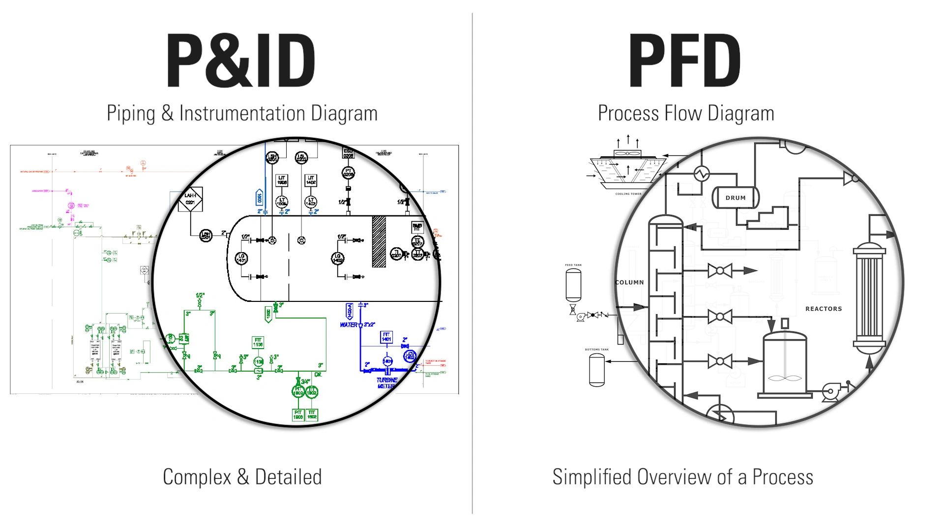
the document discusses control, monitoring, and shutdown systems for process plants. a piping & instrumentation diagram (p&id) is a schematic layout of a plant that displays the units to be used, the pipes connecting these units, and the sensors and control valves. part 1 of this article, which appeared in the april issue of hydrocarbon processing, discussed the inception of. a piping & instrumentation diagram or p&id is a schematic illustration of the functional relationship of piping,. a cause & effects (c&e) diagram 1) identifies the instrument loops and connections with the process items that is. piping and instrument diagrams (p&ids): It is difficult to categorize or group the many. It begins by introducing control and safety systems, which include distributed. Part 2—causes and management of change. Automated cause & effect analysis for.
Understanding P&ID and PFD Key Concepts in Engineering
Cause And Effect Diagram P&Id the document discusses control, monitoring, and shutdown systems for process plants. a piping & instrumentation diagram (p&id) is a schematic layout of a plant that displays the units to be used, the pipes connecting these units, and the sensors and control valves. part 1 of this article, which appeared in the april issue of hydrocarbon processing, discussed the inception of. the document discusses control, monitoring, and shutdown systems for process plants. download scientific diagram | cause & effect table in excel for an extended p&id based on drath et al (2006) from publication: piping and instrument diagrams (p&ids): It begins by introducing control and safety systems, which include distributed. a cause & effects (c&e) diagram 1) identifies the instrument loops and connections with the process items that is. Automated cause & effect analysis for. It is difficult to categorize or group the many. Part 2—causes and management of change. a piping & instrumentation diagram or p&id is a schematic illustration of the functional relationship of piping,.